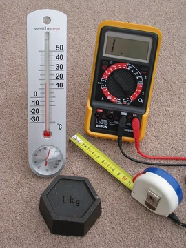
Oscilloscope
Electronic test instrument displaying voltage signals over time.

Leif Jørgensen · CC BY-SA 4.0
An oscilloscope (formerly known as an oscillograph, informally scope or O-scope) is a type of electronic test instrument that graphically displays varying voltages of one or more signals as a function of time. Their main purpose is capturing information on electrical signals for debugging, analysis, or characterization. The displayed waveform can then be analyzed for properties such as amplitude, frequency, rise time, time interval, distortion, and others. Originally, calculation of these values required manually measuring the waveform against the scales built into the screen of the instrument. Modern digital instruments may calculate and display these properties directly.
- field
- Electronic test instrumentation
- known_for
- Graphically displaying varying voltages as a function of time
- key_contributors
- Jonathan Zenneck, V. K. Zworykin
- display_element
- Cathode-ray tube (CRT)
Lore & Background
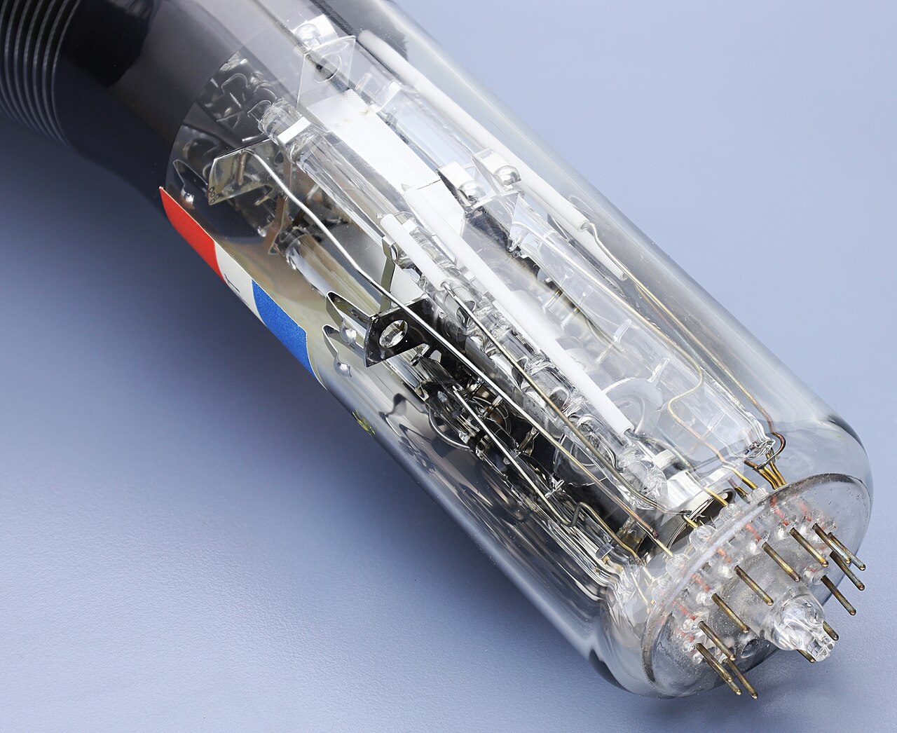
These gave valuable insights into high speed voltage changes, but had a frequency response in single kHz, and were superseded by the oscilloscope which used a cathode-ray tube (CRT) as its display element. Early CRTs had been applied experimentally to laboratory measurements as early as the 1920s, but suffered from poor stability of the vacuum and the cathode emitters. V. K. After World War II, surplus electronic parts became the basis for the revival of Heathkit Corporation, and a $50 oscilloscope kit made from such parts proved its premiere market success.
Reader's Guide
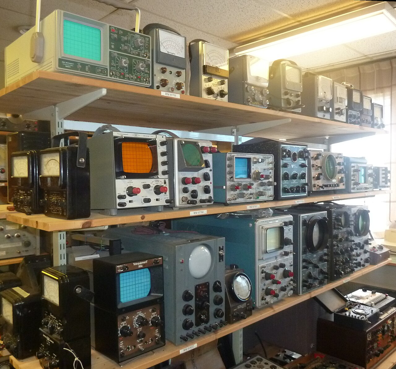
Oscilloscopes are used in the sciences, engineering, biomedical, automotive and the telecommunications industry. General-purpose instruments are used for maintenance of electronic equipment and laboratory work. Special-purpose oscilloscopes may be used to analyze an automotive ignition system or to display the waveform of the heartbeat as an electrocardiogram. An analog oscilloscope is typically divided into four sections: the display, vertical controls, horizontal controls, and trigger controls. The display is usually a CRT with horizontal and vertical reference lines called the graticule. The vertical section controls the amplitude of the displayed signal, the horizontal section controls the time base or sweep, and the trigger section controls the start event of the sweep. Most oscilloscopes are supplied with a probe, which typically has a resistor of ten times the oscilloscope's input impedance, resulting in a 0.1 (‑10×) attenuation factor to isolate the capacitive load from the signal. Most modern oscilloscopes are lightweight, portable instruments compact enough for a single person to carry. In addition to portable units, the market offers a number of miniature battery-powered instruments for field service applications. Laboratory grade oscilloscopes, especially older units that use vacuum tubes, are generally bench-top devices or are mounted on dedicated carts.
Did You Know?
- The oscilloscope was formerly known as an oscillograph.
- A $50 oscilloscope kit made from surplus electronic parts after World War II was Heathkit Corporation's premiere market success.
Purpose and Cross-Industry Applications
An oscilloscope—sometimes called a scope or O-scope—serves as a graphical window into the behavior of electrical signals over time. By plotting voltage against time, it lets engineers and scientists capture, debug, and characterize waveforms in ways that a simple multimeter cannot. From that displayed trace, a user can extract amplitude, frequency, rise time, time intervals, and distortion characteristics. In earlier analog instruments, reading those values meant carefully measuring against the graticule etched into the screen; today's digital scopes compute and display those parameters automatically, removing much of the manual estimation. The instrument family spans a remarkably wide range of industries. General-purpose units support laboratory work and routine maintenance of electronic equipment, while specialized variants tackle tasks as varied as analyzing an automotive ignition system or rendering a heartbeat waveform as an electrocardiogram. The sciences, biomedical research, telecommunications, and automotive sectors all rely on oscilloscopes as foundational diagnostic tools, making the device one of the most versatile instruments in modern technical practice.
From Electro-Mechanical Origins to the Post-War Boom
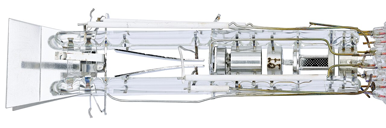
The story of the oscilloscope begins in 1893, when André Blondel introduced an electro-mechanical oscillograph capable of visualizing rapid voltage changes. Though groundbreaking, its frequency response was limited to the single-kilohertz range. The breakthrough came with the cathode-ray tube: the Braun tube appeared in 1897, and by 1899 Jonathan Zenneck had added beam-forming plates and a magnetic deflection field, establishing the fundamental CRT architecture. Experimental CRT-based laboratory measurements emerged in the 1920s, but unstable vacuum conditions and unreliable cathode emitters hampered practical use. V. K. Zworykin's 1931 design—a permanently sealed, high-vacuum tube with a thermionic emitter—finally delivered a stable, reproducible component. That stability enabled General Radio to produce an oscilloscope suitable for use beyond the laboratory. After World War II, surplus electronic parts fueled the founding of Heathkit Corporation, whose fifty-dollar oscilloscope kit became a landmark consumer success.
Analog Instrument Architecture and Control Sections
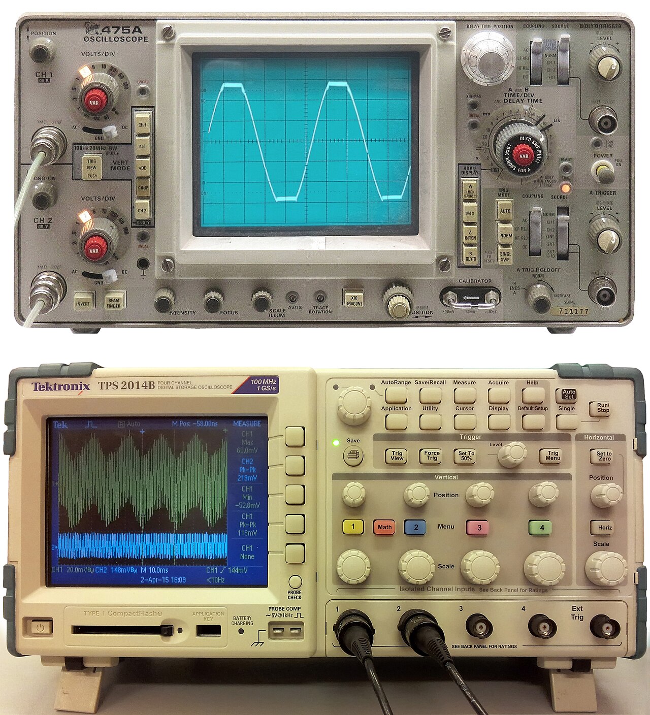
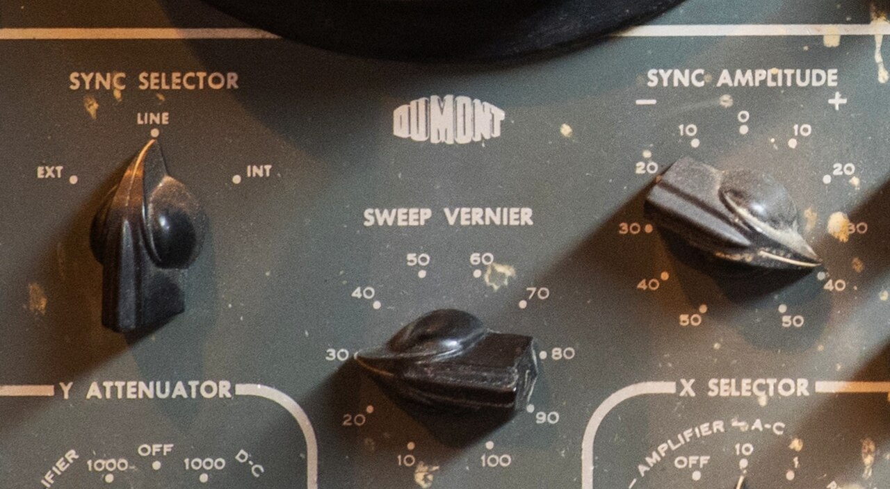
A classic analog oscilloscope is organized around four functional sections. The display, traditionally a CRT, presents a graticule of horizontal and vertical reference lines and includes controls for focus, beam intensity, and a beam-finder aid. The vertical section governs signal amplitude: a volts-per-division selector sets the scale, an AC/DC/Ground switch selects coupling, and a beam-position knob shifts the trace up or down. The horizontal section manages the time base, with a seconds-per-division switch controlling sweep speed, a horizontal input for dual X-Y plotting, and a beam-position control. The trigger section determines when each sweep begins; operators can configure it to auto-restart after every sweep or to fire on an internal or external event, adjusting source, coupling, level, and an external trigger input. Together, these four sections give the operator precise, manual control over how a waveform is captured and rendered on screen.
Probes, Impedance, and the Art of Minimizing Loading
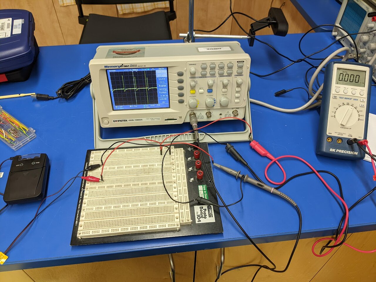
Connecting a scope to a circuit is never as simple as attaching a wire. Open flying leads pick up interference and carry high inductance, making them unsuitable for low-level or high-frequency measurements. A shielded coaxial cable solves the interference problem but introduces its own loading: a typical 50-ohm cable adds roughly 90 picofarads per meter, so a one-meter direct probe loads the circuit with about 110 picofarads of capacitance alongside a megohm of resistance. To minimize this loading, attenuator probes—commonly ten-to-one—employ a nine-megohm series resistor shunted by a small capacitor, forming an RC-compensated voltage divider matched to the cable capacitance and the scope's input impedance. General-purpose scopes typically present a one-megohm input in parallel with a known capacitance around 20 picofarads, while very-high-frequency instruments may use 50-ohm inputs requiring matched sources or active probes. The probe, then, is not an accessory but a critical part of the measurement chain.
Gallery
Frequently Asked Questions
What is an oscilloscope?
An oscilloscope is an electronic test device that plots voltage changes over time as a visual waveform on a screen. It lets engineers and hobbyists see how electrical signals behave in real time.
Who are the key figures behind the oscilloscope?
Jonathan Zenneck and V. K. Zworykin are widely credited as the principal contributors to the development of this instrument. Their work laid the groundwork for the cathode-ray tube display technology that became central to the device.
What does an oscilloscope actually show?
It renders a visual trace of one or more electrical signals, with voltage plotted against time. The resulting waveform lets the user read off characteristics like amplitude, frequency, rise time, and distortion.
What is the main purpose of an oscilloscope?
Its core job is to capture and visualize electrical signal data so that users can debug circuits, analyze performance, or characterize components. Before digital tools, operators had to manually measure the trace against the grid markings on the CRT screen.
What display technology does a traditional oscilloscope use?
Classic oscilloscopes rely on a cathode-ray tube (CRT) to paint the waveform onto the screen. This analog display element was the defining hardware component of the instrument for decades.
More in Science & Measurement 1-16
Spotted an error? Know more?
This is a living reference — every entry is fact-audited, and reader corrections feed straight into our audit queue. Suggest an edit · See this site's audit record